
Set ml directly on HMI
Servo control sets volume without timing—quicker recipe changes.
Automatic filling machines
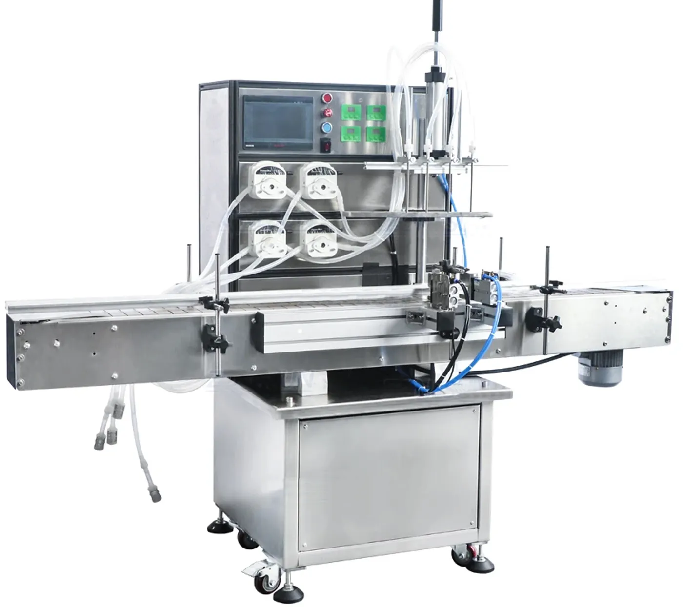
Servo‑controlled peristaltic filler with touch HMI. Dosing volume is set directly on the screen—no need to time the fill. Four peristaltic channels keep product inside disposable tubing for rapid changeovers.
Key features
Servo control sets volume without timing—quicker recipe changes.
Liquid only contacts the hose; swap tubing for changeovers.
Suitable for small bottles and healthcare liquids.
Throughput varies by product and dose.
Configure heads to match your rate today and tomorrow.
Stable transfer and automatic bottle detection.
Technical information
Performance varies by product, container and setup. Ask for a timed trial or specification review.
| Model | LUSVPP80C |
|---|---|
| Pump type | Peristaltic |
| Recommend range | ≈10–500 ml |
| Max flow | ≈2.4 L/min × 4 |
| Working capacity | ≈10–20 BPM (100 ml water) |
| Container window | Ø20–100 mm; H 50–300 mm |
| Voltage | 110/220 V, 50–60 Hz |
| Power | ≈2 kW |
| Air connector | OD 8 mm |
| Machine size | ≈2000 × 800 × 1800 mm |
| Package size/weight | ≈2070×800×1740 mm; ≈251 kg |
| Materials | Food/healthcare compatible (hose‑contact) |
Applications
Skin toner, perfume make‑up removers.
Energy shots and small PET bottles.
Solvents and reagents (compatibility dependent).
What is included
Related products
Automatic filling machines
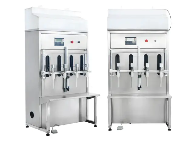
Automatic gravity filler engineered for corrosive liquids like bleach, acids and fertilizers. Non‑metal wetted parts (PP/PTFE/PVC)…
View details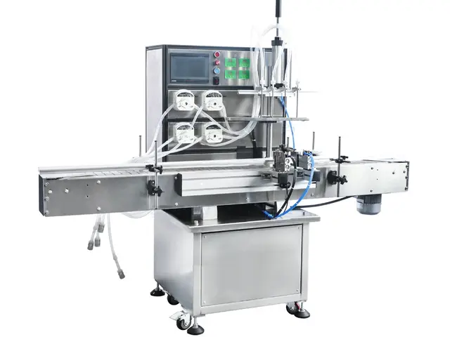
Automatic filling machines
Automatic 4‑head diaphragm‑pump filler for gels, shampoo and detergents. Large 40 L/min flow rate supports ≈30–45 bpm with four…
View details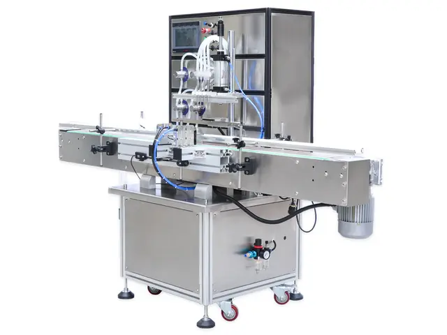
Automatic filling machines
Equipped with a gear pump, this liquid filling machine can work automatically. The machine can fill about 30 bottles/min (at 5L). Each…
View detailsApplication and acceptance guidance
This automatic machine uses four peristaltic channels and keeps product within the replaceable tubing path. The arrangement can support clean changeovers and controlled doses for compatible liquids, but the tube specification, source height and priming method are part of the metering system. They should be fixed in the production setup rather than treated as incidental consumables.
The existing page gives a recommended range and reference performance. Confirm the required application with the actual tube, liquid, container and nozzle. Small doses are especially sensitive to bubbles, tube variation and end-of-fill settings, while higher flow can be constrained by suction conditions and nozzle restriction.
Record material, bore, wall, length, routing and replacement reference. Chemical compatibility and mechanical recovery must both be suitable. Verify fills after tube replacement or a changed routing.
Minimise unplanned suction lift and air entry. Define source vessel, connection, filter and refill level so all channels prime consistently and remain supplied through the batch.
Set the dose on the HMI, then sample each channel separately. Adjust using the approved calibration method and recheck after warm-up, a pause and any tube change.
Specification and trial evidence
Use the proposed production tube and nozzle throughout the test.
| Selection point | What to define or test | Why it matters |
|---|---|---|
| Tube fit | Install the specified tube with repeatable routing and compression | Creates the intended metering geometry. |
| Prime | Remove visible air and confirm stable product at every nozzle | Prevents compressible bubbles affecting dose. |
| Calibrate | Measure every channel at the required fill quantities | Confirms individual head settings. |
| Run continuously | Observe source level, tube movement, nozzle drip and container handling | Tests sustained operation rather than isolated shots. |
| Pause and restart | Hold for a representative stop and restart normally | Checks delayed drip, drainage and the first fills after a pause. |
| Change product path | Replace or clean the tube and verify the restored setup | Measures practical changeover and post-maintenance control. |
Buyer questions
The rollers displace product by compressing the tube, so bore, wall, material and recovery influence the amount moved per cycle. Use the approved tube and verify replacements.
Prime and calibrate each channel individually, then check them together under the same source and nozzle conditions. Retain head-specific adjustment values where used.
Loose connections, excessive suction lift, low source level, vortexing or air already in the product can introduce bubbles. The source and priming procedure should be part of the trial.
Suitability depends on viscosity, tube, suction, dose and required rate. Test the actual product; a piston or another positive-displacement method may be more practical for some thick liquids.
Install the new or cleaned product path using the documented route, prime, calibrate and approve the first fills before releasing production.
Include tube identity, product temperature, source arrangement, each channel’s results, nozzle cleanliness, output conditions and stop/restart checks.
Machine demonstration
The clip shows the physical arrangement of the pump heads, tubing, nozzles and conveyor. It does not replace calibration with the approved tube and production liquid.
Automatic four-channel peristaltic filler with tubing routed from the pump heads to the filling nozzles.
Keep tube material, bore, wall, length and routing consistent between channels. Unequal bends, compression or replacement tubing can change priming and the quantity displaced by each pump head.
Check for bubbles, drainage and movement after stopping. The source height and priming method should be documented so the same product condition can be restored after a tube change.
Observe simultaneous start and stop, residual droplets and bottle alignment. Calibrate every channel after the final tube and nozzle arrangement has been fitted.
The machine is shown with four peristaltic pump heads mounted above the conveyor. Tubes run from the pump heads to four nozzles aligned over a group of bottles while the automatic filling station operates.
Technical guidance
Control tubing, product condition, small-pack handling and acceptance evidence.
Confirm tubing and connectors against product and cleaning conditions.
Read guideTest dose range, tubing installation, priming and restart.
Read guideProve small bottle sensing, neck alignment and indexing.
Read guideRecord each channel, recipe and operating state.
Read guide